

Parking Brake Adjusters
|
Parking Brake Adjusters |
Calipers with parking brake adjuster need to be a bit more complicated
than adjusters for drum brakes because the deflection of the casting under load
is more than the running clearance. This means that a simple adjuster would
over-adjust after a high pressure stop and cause the brake to drag.
The fix for this problem is to prevent the adjuster from working when the line
pressure has risen above a few bars.
Every caliper supplier has their own method of doing this, many of them patented
but the outcome is very similar. This is a description of one such adjuster
designed by Nissin but also used by Lucas.
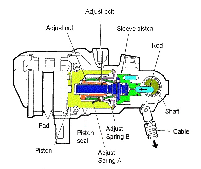
As the brake pressure rises the piston starts to move, bringing with it the adjust
nut due to the action of adjust spring
A. Clearance in the thread on the adjust
bolt ensures normal running clearance. As the pressure continues to rise
and the caliper starts to deflect the pressure act to the right on the adjust
bolt holding the cone clutch on the sleeve
piston closed preventing the adjust
bolt from turning to adjust the brake. Should the caliper require adjustment
then the adjust nut will engage with
the thread flanks on the adjust bolt before substantial pressure has been achieved.
This will cause the cone clutch on the sleeve
piston to open and the adjust bolt will turn and increase the strut length. The next time the parking brake is
used the shaft rotation will have been
reduced. In practice wear adjustment is continuous and no noticeable change
in cable travel will be detected.
The thread form on the adjust bolt uses
different flank angles on each side, typically 45 ° on the compression side
and 15 ° on the adjust side, this minimises the torque generated in the cone
clutch when the strut is under load.
The Lucas / Meritor truck hydraulic caliper adjuster is similar:-
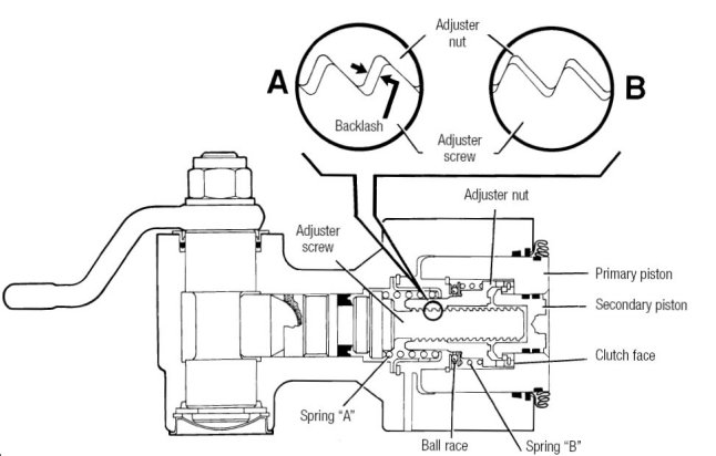
This mechanism is "one-shot" in operation and does not over adjust
during high pressure applications. The adjuster is only operated during a foot
brake application and not during handbrake application.
Within the primary piston the adjuster nut is retained by spring "B", a ball
race, a washer and a circlip. Also within the piston is a secondary piston which,
when the hydraulic pressure is applied, is capable of exerting an end load on
the adjuster nut holding it against the clutch face. The adjuster screw sits
in the base of the housing and is prevented from turning by its head profile
(not shown) which locates in a mating form in the housing. The spring retainer,
held by a circlip, causes spring "A" to exert an effort onto the flange of the
adjuster screw holding it against the cam and strut. Square hydraulic seals
are fitted in the cylinder bore and on the secondary piston and a lip seal is
fitted to the strut.
If no adjustment is required each hydraulic brake application causes the piston
and nut assembly to move forward until the adjuster thread backlash is taken
up, typically 0.6mm. By which time the brake pressure will have reached 10 to
15 bar and the secondary piston will be holding the adjuster nut against the
clutch face with such a force that rotation is not possible. A brake pressure
above this requires the piston assembly to move still further to allow for deflections
of the caliper housing and pad compression etc. Spring A must be overcome to
achieve this and the adjuster screw moves forward as one with the piston assembly
and no adjustment takes place. (The adjuster screw cannot rotate due to the
shape of its head and the adjuster nut is locked against the clutch face by
the pressure imbalance on the secondary piston).
During a high pressure stop the primary piston could move forwards by about
2mm, clearly, if adjustment were to take place the brake would become locked
on.
If adjustment of the handbrake is required the piston and nut assembly will
move forward until the adjuster thread backlash is taken up, at this point however
the hydraulic pressure generated will be low and the adjuster nut will not be
locked against the clutch face. Further forward movement of the primary and
secondary piston causes the clutch face to open because the adjuster screw is
still being held firm by return spring A. The adjuster nut then rotates under
the influence of spring B and the ball race. The adjuster nut will only stop
rotating when the adjuster screw reseats or the hydraulic pressure reaches 10
to 15 bar and the secondary piston is able to lock the clutch face. Any further
increase in pressure will cause the adjuster screw to be pulled forward and
spring A will be overcome.
When the parking brake is applied the adjuster is loaded on a 45 degree thread
flank angle and much less torque is generated, this combined with the clutch
friction prevents rotation and the locked assembly pushes the primary piston
forward applying the brake.
© Engineering Inspiration