

|
| Drum Brakes |
Technical information about drum brakes appears to be a little light on the Internet so here's a bit of background on the theory of them. It was mainly written with cars in mind but the principles for a motorcycle are the same if not simpler due to the lack of a parking brake. The bikes I've owned have all had pinned shoes although I'm not sure why. My MZ always had problems with the rear brake locking on when it was cold, understanding this theory explains why and point the way to solving the problem with a file and a face mask!
CENTRE OF MAXIMUM PRESSURE (CMP)
A drum brake for road vehicles consists of a number of lined shoes located within a drum that rotates with the wheel. To slow or stop the vehicle the shoes are pressed against the inside surface of the drum to create a friction force. Correct drum brake geometry is important in order to ensure that:
· Brake linings wear evenly.
· Brake output torque is appropriate to the application.
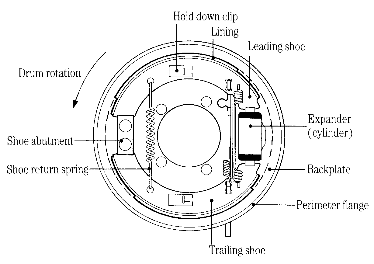
Figure 1 The major drum brake components
Figure 1 shows a typical arrangement of the shoes and other stationary
components in a drum brake. The whole assembly is mounted on the back plate.
For clarity, only the inner surface of the drum is indicated, but in practice
its rotating outer surface is very close to the back plate perimeter flange.
The small clearance between them reduces the risk of dust, water and foreign
bodies entering the drum. The brake shoes shown in Figure 1 are forced apart
and into contact with the drum by the small hydraulic cylinder, or expander,
shown on the right. They pivot about the shoe abutment on the left and are restored
to the 'brakes off' position by the shoe return springs.
From Figure 1 you will see that, with the drum rotating in the direction shown, the upper shoe is ahead of its pivot point. It is said to be a leading shoe. Similarly the lower shoe trails behind its pivot point and is called a trailing shoe. There is an important difference in the way leading and trailing shoes act under braking.
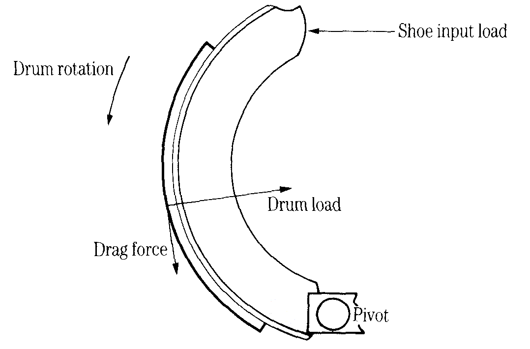
Figure 2 Leading shoe
Figure 2 shows the forces acting when a leading shoe is applied. Notice that the frictional drag force has a moment about the pivot point. This increases the input load and hence increases the drag. In other words, there is a self-servo action, which increases the braking effect.
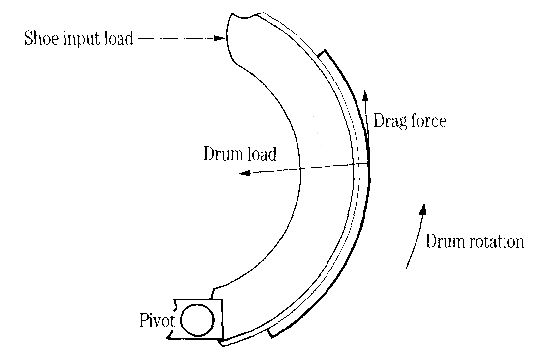
Figure 3 Trailing shoe
Figure 3 shows the forces acting when a trailing shoe is applied. In this case the moment of the frictional drag force about the pivot point opposes the input load, thereby reducing the drag and the braking effect.
One end of each shoe locates at a fixed point on the brake back
plate. This is done in one of two ways:
· In the sliding (or floating) shoe type the end of the shoe has a radius, which
can roll or slide on a flat surface perpendicular to the back plate. It is held
against the surface by the shoe return springs.
· In the pinned shoe type the shoe pivots about a post mounted on the back plate.
Figure 4 Sliding shoes
Sliding shoes give a degree of self-alignment so the linings can be ground to the drum diameter during manufacture without the risk of the shoes grabbing. This also means that the bedding-in period is relatively short.
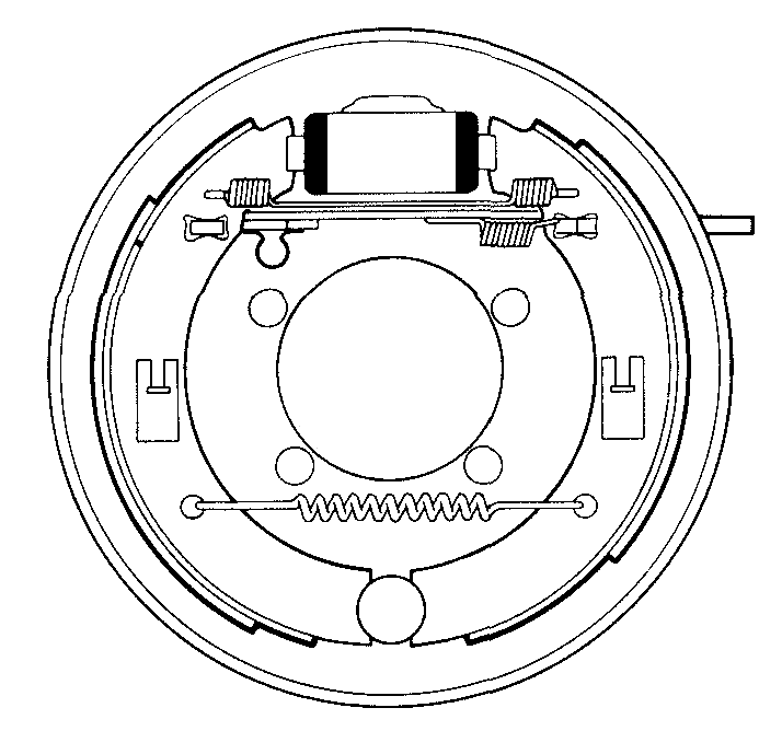
Figure 5 Pinned shoes
In contrast the pinned shoe brake (Figure 5) must have its linings crown ground, i.e. ground to a smaller diameter than the drum. This ensures that the centre of the lining always touches the drum first, until the lining is fully bedded in. If the leading edge of the leading shoe were to touch the drum first the brake would grab. The principles of 'grabbing' is explained later.
The geometry of a drum brake is determined by the relationships
between the various forces acting when the brake is applied. The most fundamental
of these are:
· The coefficient of friction
· The shoe factor
· The centre of maximum pressure (CMP).
When two surfaces in contact have relative movement their coefficient of friction is defined as:
COF = friction force opposing relative movement / load perpendicular
to the sliding surfaces
As far as drum brakes are concerned the coefficient of friction is:
COF=drag force / drum load
Its value depends on:
· The materials of the drum and brake lining
· The physical condition of the surfaces
· The absence of foreign matter between the surfaces - oil, dust, etc.
· Their temperature
The coefficient of friction for most brake lining/drum combinations is in the
range 0.25 to 0.45.
Like the coefficient of friction, the shoe factor relates the force applied to the drag force produced. However, it takes account of the leverage due to the cylinder acting on the end of the shoe.
Shoe factor is defined as:
SF - drag force / Shoe input load
Its value depends on:
· The coefficient of friction between drum and lining
· The arc length and angular position of the lining
· Whether the shoe is leading or trailing
· The type and position of the shoe mounting, i.e. pinned or sliding
· The position and angle of the abutment
The coefficient of friction (which, as we have seen, is variable) has a profound effect on the shoe factor, particularly for a leading shoe.
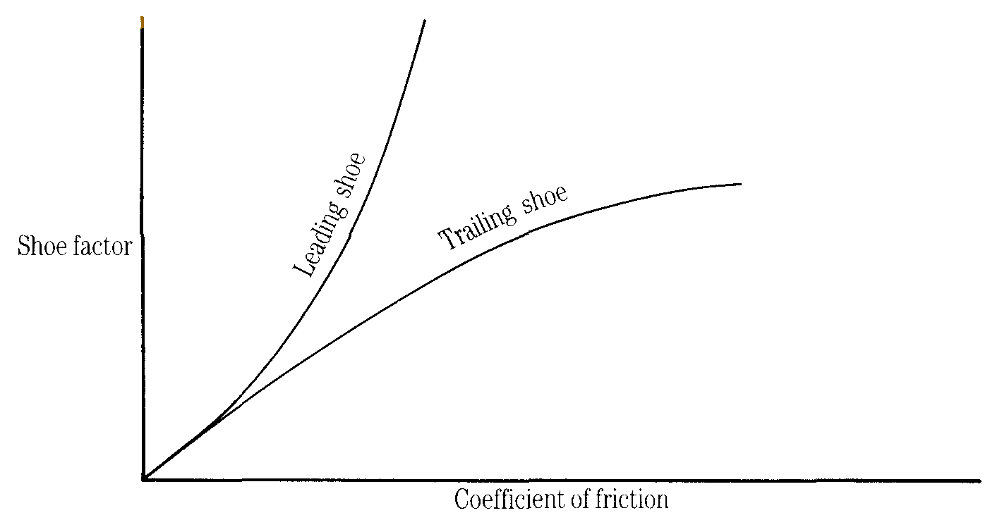
Figure 6 Graph showing the effect of friction on shoe factor
Centre of maximum pressure (CMP)
When a brake is designed the drum and shoe are treated as rigid bodies and the lining material is assumed to be perfectly elastic, i.e. its deformation is proportional to the stress induced by the applied load. This is commonly known as Hookes' law. This analysis produces a pressure distribution curve that is sinusoidal about a radial line through the centre of maximum pressure.
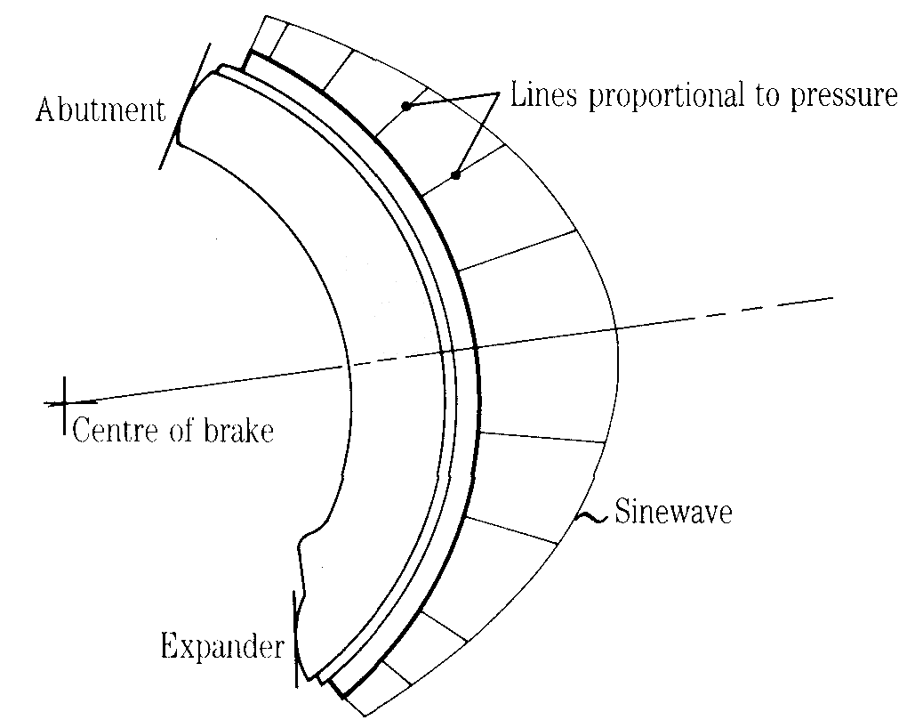
Figure 7 Diagram showing pressure distribution curve
The position of the CMP is not necessarily at the mid point of the lining arc. In fact, its position varies as the lining wears. But the brake should be designed so that the CMP is at midpoint of the lining arc in the fully worn condition. This gives maximum lining life because the least material is left when replacement shoes are needed.
A brake is said to grab when it has an unusually high shoe factor, making fine control difficult or even impossible. A spragging brake locks solid as soon as it is applied, i.e. it then has an infinite shoe factor. Obviously a spragging drum brake on a road vehicle would be disastrous, since wheel locking would follow even with the slightest application of the brakes. Fortunately, owing to the position of the resultant force, it is almost impossible to design a conventional drum brake, which will sprag under normal conditions. Figure 8 shows how the resultant force on the brake shoe determines whether the brake will sprag, grab or behave normally.
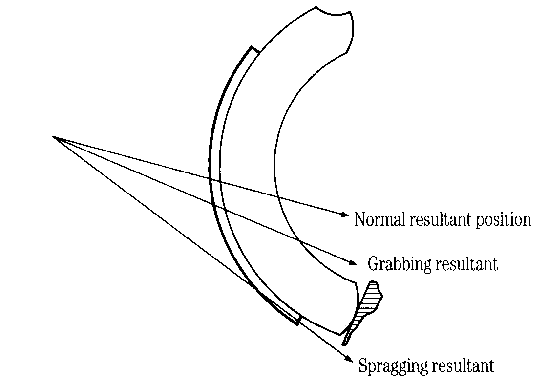
Figure 8 Diagram showing possible shoe resultant positions
Irregular lining wear or unbedded linings are the usual cause
of grabbing. They result in tip (leading edge) contact, which brings the resultant
force nearer to the pivot or abutment.
Irregular lining wear often results from repeated high deceleration stops. The
high temperatures accelerate shoe wear and expand the drum so that the lining
wears to a larger radius profile. Lining materials have a low coefficient of
thermal conductivity, which prevents the shoes from reaching drum temperature
and so, on cooling, the lining is left with a larger diameter than the drum.
Tip contact is then inevitable.
Grabbing is sometimes experienced when a vehicle has been standing overnight.
Linings tend to absorb moisture from the atmosphere, which causes slight swelling
and an increase in diameter. It also increases the coefficient of friction.
This phenomenon is often termed 'early morning sharpness'. These conditions
may cause the brake to sprag leaving the shoes locked on when the parking brake
is released. They can be released by moving the vehicle in the opposite direction.
© Engineering Inspiration